Sunny Fabrics | Conductive Foam, Tape & EMI Shielding Can Manufacturer
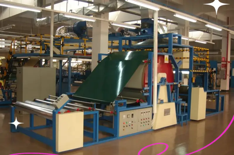
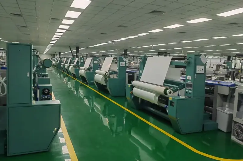
- We specialize in the design and manufacturing of conductive foam, conductive tape, EMI shielding cans and functional fabrics.
- We specialize in the design and manufacturing of conductive foam, conductive tape, EMI shielding cans and functional fabrics. Our R&D and production team supports customized programmes from material specification through to the delivered part.
1. Customized Product Solutions
- Material and formulation customization to meet different performance requirements
- Thickness, weight and dimension tailored to specific applications
- Functional treatment for ESD, EMI, grounding or RFID targets
- Custom width and density to optimize production efficiency
- Application-specific engineering support from sample to mass production
2. OEM and ODM Services
- Customized logo and label printing for brand identification
- Packaging design to upgrade product and brand value
- Specification and structure development for various applications
- Functional formula development for stable and reliable performance
- In-house tooling and converting support for custom part formats
Custom Die-Cut Conductive Foam Gaskets Manufacturer
Custom die-cut conductive foam gaskets are precision-converted components designed for electronic equipment, communication devices, electrical enclosures and other industrial applications. Unlike standard foam materials supplied in sheets or rolls, die-cut conductive foam gaskets are manufactured according to specific drawings, dimensions and application requirements. They can be produced in various shapes, thicknesses and configurations to meet the needs of different OEM and ODM projects.
For electronic manufacturers, the dimensions and geometry of a gasket can directly affect its installation, compression and electrical contact conditions. A material that appears suitable in a general specification may not perform as expected if its shape, thickness or positioning does not match the assembly design. Custom die-cutting helps transform conductive foam materials into components with defined outlines, openings, cutouts and other geometric features.
Sunny Fabrics supplies conductive foam materials and customized converting solutions for B2B customers. We work with project requirements involving custom dimensions, material selection, die-cut shapes and production specifications. Customers can provide CAD drawings, PDF files, physical samples or detailed measurements as the basis for product evaluation and manufacturing discussions.
Our custom manufacturing approach is intended for electronic component manufacturers, EMI shielding material distributors, communication equipment suppliers, industrial electronics manufacturers and OEM/ODM purchasing teams. Whether a project requires simple rectangular foam components or more complex die-cut designs, the manufacturing requirements should be reviewed according to the selected material, drawing details, dimensional tolerances and expected production volume.
Custom die-cut conductive foam gaskets can help simplify component assembly, reduce manual cutting work and improve dimensional repeatability when the manufacturing process is properly specified. The final solution depends on the material construction, converting method and functional requirements of the finished application.
1. Introduction to Custom Die-Cut Conductive Foam Gaskets
Custom die-cut conductive foam gaskets are conductive foam components processed into specific shapes and dimensions. They are designed for applications where a flexible foam material with electrical properties needs to fit a defined position within an electronic or industrial assembly. Their geometry can be adapted to match the customer's product structure, available installation space and functional requirements.
The term die-cut refers to a converting process in which a cutting tool is used to produce a predetermined shape from sheet or roll material. Depending on the design and production requirements, the finished component may include straight edges, rounded corners, internal openings, slots, notches or other features. The cutting process is selected according to the material, component geometry, required tolerance and production quantity.
Compared with purchasing general-purpose foam material and cutting it manually, custom die-cutting can provide a more consistent component format for repeated manufacturing. It may also reduce material handling and simplify assembly operations. These advantages are particularly relevant to OEM customers producing electronic equipment in regular batches.
The electrical and mechanical characteristics of the finished gasket depend on the selected conductive foam grade. Different products may use different substrates and conductive constructions. Some materials have conductive surface treatments, while others may incorporate conductive components in another way. Therefore, the exact material grade and its relevant test data should be confirmed before production approval.
For a successful project, the customer should define both the component geometry and its intended function. Important considerations may include the electrical contact requirement, compression range, installation position, operating environment and compatibility with surrounding components. These details help determine whether a particular conductive foam material and die-cut design are appropriate.
2. What Are Die-Cut Conductive Foam Gaskets?
A die-cut conductive foam gasket is a processed foam component manufactured to a specified outline. It combines the physical characteristics of a foam material with electrical properties intended for a defined application. The component may be installed between two surfaces, positioned around an electronic component or used in another part of an assembly where its material properties are required.
The main purpose of custom die-cutting is to produce a component that matches the customer's design. Instead of receiving a large sheet that must be cut and adjusted internally, the customer receives material in a predetermined shape. This can help reduce additional manufacturing steps and improve consistency between individual components.
Die-cut conductive foam gaskets may be designed as solid pieces, frames, strips, rings or more complex outlines. Some designs contain internal openings to accommodate connectors, screws or other mechanical features. Others require multiple cutouts to match the layout of an electronic housing or assembly surface.
The term gasket can cover different component designs. Not every die-cut conductive foam part is used in the same way, and not every component provides identical EMI shielding performance. A conductive foam gasket may be used as part of an electrical contact arrangement, a shielding design or another functional assembly. Its suitability depends on the complete application and should be validated by the customer's engineering team.
When sourcing these components, buyers should review the material specification and the drawing together. The drawing defines the geometry, while the material specification defines the relevant electrical and mechanical characteristics. Both are necessary for accurate quotation, sample production and repeat manufacturing.
3. Types of Custom Die-Cut Foam Components
Custom die-cut conductive foam gaskets can be manufactured in different shapes according to the customer's design. The shape is determined by the installation location, the available space and the required functional contact area. The following are common design categories used in customized foam converting projects.
3.1 Rectangular Die-Cut Foam Gaskets
Rectangular gaskets are among the most straightforward die-cut designs. They are used where the required component has a simple length and width and does not need complex internal features. Rectangular shapes can be suitable for electronic assemblies, equipment housings and other applications where a flat foam component is required.
Although the outline is simple, the dimensional requirements may still be important. Length, width, thickness and corner conditions should be clearly defined. If the gasket is installed in a narrow space, even small dimensional differences may influence fit or positioning.
3.2 Square Die-Cut Foam Gaskets
Square foam components are used in applications where equal or nearly equal side dimensions are required. They may serve as individual contact pieces, cushioning sections or functional material inserts. The design should specify the nominal dimensions and acceptable tolerances for each side.
For repeat production, consistent cutting and accurate material thickness help ensure that the components can be handled and installed in a predictable way.
3.3 Circular and Ring-Shaped Components
Circular die-cut foam components may be required around connectors, fasteners, openings or other round features. Ring-shaped designs include an external diameter and an internal opening. Both dimensions should be specified because the relationship between the outer and inner profiles determines the available material area.
Customers should also clarify whether the ring requires a concentric opening, a specific edge condition or any additional features. If the component must fit around a mechanical feature, a physical sample or detailed drawing can help reduce design ambiguity.
3.4 Foam Gaskets with Internal Cutouts
Some electronic assemblies require foam components with one or more internal openings. These cutouts may accommodate connectors, screws, mounting points or other components. Their dimensions and positions should be defined accurately in the drawing.
When a design includes several openings, the distance between each opening and the external edge may become a critical dimension. Buyers should identify these features clearly and indicate which dimensions require tighter control.
3.5 Irregular and Custom-Shaped Components
Irregular foam components are designed for applications where standard geometric shapes cannot match the required installation area. These parts may include angled edges, curved sections, stepped outlines, multiple cutouts or other customized features.
For complex shapes, a CAD drawing is usually the most useful reference. It helps communicate the intended geometry and provides a basis for reviewing cutting feasibility, material utilization and dimensional requirements. Where the drawing contains very small features or narrow sections, the supplier may need to review whether the selected material and process can achieve the required result.
3.6 Multi-Piece Die-Cut Sets
Some projects require several different foam components that are installed together in one product. These components may have different sizes or shapes but share the same material specification. They can be managed as a coordinated die-cut set according to the customer's drawing and packaging requirements.
For multi-piece projects, each component should have a clear identification reference. This helps avoid confusion during sampling, quotation, production and incoming inspection. The customer may also specify the number of pieces per set and the preferred packaging arrangement.
4. Die-Cutting Technologies for Conductive Foam
The die-cutting method influences the achievable shape, dimensional accuracy, production efficiency and processing cost. The most suitable method depends on the material construction, thickness, design complexity and order quantity. A manufacturing process should be selected after reviewing the complete drawing and the intended material grade.
4.1 Steel Rule Die Cutting
Steel rule die cutting uses a shaped cutting tool to cut material into a predetermined outline. It is commonly considered for repeat production of components with established dimensions and relatively consistent designs. The cutting tool is prepared according to the component geometry and used to produce repeated parts.
This method may be suitable for projects where a customer expects ongoing demand and requires a consistent component shape. Tooling requirements and production economics should be evaluated according to the part size, design complexity and expected order volume.
For a new project, customers should confirm the drawing revision and critical dimensions before tooling is prepared. Changes to the outline or internal features after tooling approval may require additional review or tool modification.
4.2 Precision Die Cutting
Precision die cutting focuses on producing components with defined dimensional requirements. It may be considered where the design includes important fitting dimensions, narrow sections or multiple features that must remain consistent. The achievable accuracy depends on the material and the selected production process.
Buyers should distinguish between nominal dimensions and critical tolerances. Not every feature on a drawing requires the same level of accuracy. Identifying the dimensions that directly affect assembly can help establish realistic manufacturing and inspection requirements.
4.3 Digital Cutting for Prototypes
Digital cutting may be considered during prototype development or for designs that require frequent revisions. It can be useful when a customer wants to evaluate a component shape before committing to dedicated tooling. The suitability of this process depends on the material thickness, cutting requirements and available equipment.
For engineering samples, digital cutting can help support early design evaluation. Once the design is confirmed, the customer and supplier can review whether another converting method is more appropriate for regular production.
4.4 Multi-Layer Cutting
Some projects involve materials supplied in multiple layers or constructions that require additional processing. Multi-layer cutting may be possible depending on the material combination, thickness and required edge condition. The process should be reviewed carefully to ensure that the layers remain properly aligned and that the finished part meets the intended requirements.
Customers should identify all layers in the technical drawing or material specification. If the design includes adhesive backing or a release liner, the supplier should confirm how these layers will be handled during cutting and packaging.
4.5 Process Selection According to Order Volume
Prototype and mass-production requirements may justify different processing methods. A low-volume sample project may prioritize design flexibility and short development cycles, while a high-volume program may place greater importance on production efficiency, tooling cost and repeatability.
For this reason, the expected quantity should be discussed during quotation. A supplier can then review the available process options and explain any tooling or setup requirements that may affect the total project cost.
5. Custom Shapes and Design Options
One of the main reasons OEM customers choose die-cut conductive foam gaskets is the ability to manufacture components according to a specific product design. Custom shapes allow foam material to fit defined spaces and accommodate nearby mechanical or electronic features.
5.1 External Profiles
The external profile defines the overall outline of the gasket. It may be rectangular, circular, polygonal, curved or irregular. The external profile should be clearly represented in the drawing, with dimensions provided for all important edges and transitions.
Where the component has curved or angled sections, customers should provide the relevant radius, angle or coordinate information. Clear drawing details help reduce the possibility of misunderstanding during quotation and sample development.
5.2 Internal Openings and Cutouts
Internal openings may be required for screws, connectors, mounting structures or other assembly features. Their position can be just as important as their size. A drawing should identify the dimensions of each opening and its location relative to a defined reference edge or center point.
For multiple openings, consistent numbering or feature identification can help ensure that each cutout is interpreted correctly. If a particular opening has a special tolerance, this should be stated separately.
5.3 Slots and Notches
Slots and notches can help a foam component fit around nearby structures or allow a particular installation method. Their width, length and position should be specified. Very narrow features may require additional manufacturing review because material flexibility and cutting conditions can affect the finished shape.
5.4 Rounded Corners and Edge Design
Rounded corners may be required to match the enclosure design or reduce interference during installation. The corner radius should be identified in the drawing where it is important to the application. If the design permits a general corner treatment, this should also be stated to avoid unnecessary ambiguity.
5.5 Orientation and Reference Features
Some die-cut components are not symmetrical and must be installed in a specific orientation. In these cases, reference marks, orientation notes or clear drawing views may be necessary. This is particularly useful when the component contains several openings or different edge features.
For multi-component assemblies, each part should have a unique part number or drawing reference. This makes it easier to manage revisions and prevents similar-looking parts from being mixed during production.
6. Material Selection for Die-Cut Conductive Foam Gaskets
Material selection is a critical part of custom gasket development. The selected foam must be compatible with the component design, intended electrical function and mechanical conditions. A material that can be cut into the required shape may still be unsuitable if its electrical or compression characteristics do not meet the application requirements.
6.1 Conductive Foam Construction
Conductive foam is a general material category rather than one single construction. Different grades may use different foam substrates and conductive treatments. Some products rely on conductive surface characteristics, while others may have a different conductive structure.
For this reason, buyers should request information about the exact material grade being proposed. The material description should be supported by relevant electrical and mechanical data where those properties are important to the application.
6.2 Foam Flexibility
Flexibility influences how the component behaves during cutting, handling and installation. A flexible grade may be suitable for designs that require the gasket to adapt to a particular assembly space. However, excessive flexibility may create handling or positioning challenges for certain small components.
The material should be evaluated in the final component dimensions rather than only as a large sheet. Narrow sections, small openings and complex outlines may behave differently from the unprocessed material.
6.3 Compression Characteristics
Compression behavior is important when the gasket is installed between two surfaces. The material may be compressed to establish contact or occupy a defined space. The required compression range should be considered together with the available installation gap and the mechanical load applied to the assembly.
Buyers should provide information about the expected compression condition where possible. This allows the material selection process to consider both the initial thickness and the mechanical response under installation pressure.
6.4 Electrical Resistance Requirements
Electrical requirements should be defined according to the intended function. Surface resistance, volume resistance and electrical contact behavior describe different properties. They should not be treated as interchangeable measurements.
If the component is intended for an EMI-related application, resistance data alone may not demonstrate the shielding performance of the complete assembly. The buyer should identify the relevant shielding requirement and determine whether material-level or finished-assembly testing is necessary.
6.5 Material Compatibility
The gasket may contact metal, plastic, coated surfaces or other materials. Compatibility should be reviewed according to the intended installation environment. If adhesive backing is required, the adhesive and the surface to which it will be applied should also be considered.
For projects involving demanding environmental conditions, buyers should provide relevant information about temperature, humidity, exposure and expected service life. Material suitability should be validated using appropriate testing for the application.
7. Thickness, Dimensions and Tolerances
Dimensions and tolerances are central to the manufacturing of custom die-cut conductive foam gaskets. The finished component must match the customer's design while remaining suitable for the selected material and processing method. A complete drawing should identify the nominal dimensions and any critical tolerances.
7.1 Thickness Selection
Thickness influences the amount of material available for compression and the space occupied by the gasket. The appropriate thickness depends on the installation gap, required contact condition and mechanical characteristics of the selected foam. Customers should avoid choosing thickness based only on the appearance of a sample.
Nominal thickness and actual measured thickness may differ within an agreed tolerance. Because foam materials are compressible, the measurement method should be defined when thickness is a critical specification.
7.2 Length and Width
Length and width define the overall dimensions of many die-cut components. For rectangular parts, these dimensions are relatively straightforward. For irregular shapes, the drawing should provide sufficient information to define the external profile accurately.
Customers should identify which dimensions directly affect installation. These dimensions may require closer inspection than features that have no significant effect on fit or function.
7.3 Hole and Cutout Tolerances
Internal openings and cutouts should be specified with clear dimensions and positions. If the component fits around a connector or mounting feature, the opening size may be a critical characteristic. The tolerance should account for both the required fit and the practical behavior of the selected material.
7.4 Edge and Profile Accuracy
Edge quality may affect installation, appearance and material handling. Depending on the design, buyers may require clean cut edges, consistent corner radii or accurate alignment between internal and external features.
Where a design contains narrow bridges or small projections, the supplier should review whether the selected material and cutting method can maintain the required geometry. A design review before sampling can help identify potential processing limitations.
7.5 Defining Critical Dimensions
Not every dimension needs the same tolerance. A practical drawing should identify critical dimensions separately from general dimensions. This makes it easier to establish inspection priorities and helps avoid unnecessary manufacturing complexity.
For OEM projects, a controlled drawing revision should be used as the reference for quotation, sample approval and production. Any design changes should be documented and approved before the next manufacturing stage.
8. Adhesive Backing and Lamination Options
Some custom die-cut conductive foam gaskets require adhesive backing to support positioning or installation. Adhesive-backed components may help reduce movement during assembly and simplify handling. However, adhesive selection depends on the foam surface, application conditions and the customer's assembly process.
8.1 Pressure-Sensitive Adhesive Backing
Pressure-sensitive adhesive can be considered when a gasket needs to be attached to a designated surface. The adhesive may be supplied as a layer on one side of the foam component. The suitability of the adhesive depends on the substrate, surface energy, operating environment and required bonding performance.
Buyers should specify whether adhesive is required on one side or both sides. They should also identify the surface to which the gasket will be attached and provide any special requirements related to repositioning or removal.
8.2 Release Liner Options
A release liner protects the adhesive before installation and allows the user to remove the backing during assembly. The liner format may influence how the die-cut component is handled and installed. Depending on the design, the liner may remain as a single sheet or be prepared with a feature that makes removal easier.
For production programs involving many small components, liner handling can be an important part of assembly efficiency. Buyers should describe the preferred installation method when discussing the adhesive-backed design.
8.3 Single-Sided and Double-Sided Adhesive
Single-sided adhesive is generally considered when the gasket needs to be fixed to one surface. Double-sided adhesive may be considered when bonding or positioning is required on both sides. The appropriate option depends on the assembly design and should not be selected without checking material compatibility.
8.4 Lamination with Other Materials
Some projects may require conductive foam to be combined with another functional material. Lamination can be considered where the material combination and application support it. The additional layer may influence total thickness, flexibility, bonding behavior and cutting characteristics.
Customers should provide the complete layer structure and identify the function of each layer. The finished construction should be evaluated as a complete material system rather than treating each layer independently.
8.5 Adhesive and Assembly Validation
Adhesive performance should be evaluated under the conditions expected during installation and use. Relevant considerations may include bonding strength, surface preparation, temperature and exposure conditions. The customer should validate the adhesive-backed gasket in a representative assembly before approving mass production.
9. EMI Shielding and Electrical Contact Applications
Custom die-cut conductive foam gaskets may be used in electronic designs where conductive contact or shielding-related functions are required. Their effectiveness depends on the material properties and the way the component is integrated into the complete assembly.
9.1 Conductive Contact Between Surfaces
In some electronic assemblies, conductive foam is used to establish contact between two surfaces. The gasket's dimensions, compression behavior and surface characteristics can influence the contact condition. The surrounding materials and installation pressure are also important.
For this type of application, the engineering team should define the required contact area and the expected compression range. A prototype should be installed in a representative assembly to confirm that the component fits correctly and provides the intended electrical behavior.
9.2 EMI-Related Enclosure Designs
Electronic enclosures may use conductive components as part of an electromagnetic compatibility design. A die-cut foam component may be considered where its geometry and material characteristics match the enclosure interface. However, the presence of a conductive foam gasket does not automatically guarantee a particular shielding effectiveness.
Shielding performance can depend on frequency, enclosure design, contact continuity, gaps, assembly pressure and other factors. If the project has a specific shielding target, the complete design should be evaluated using an appropriate test method.
9.3 Grounding and Electrical Continuity
Some designs require a conductive component to contribute to an electrical continuity path. In these cases, the material's resistance and the contact condition should be reviewed together. A material-level measurement may be useful, but the actual assembly should also be tested where electrical continuity is a critical requirement.
9.4 ESD-Related Component Applications
Conductive foam components may also be considered for selected static-control applications. The required material classification depends on the protection strategy and the sensitivity of the electronic components. Buyers should distinguish between conductive and dissipative materials and request test information appropriate to the intended use.
9.5 Application-Specific Performance Testing
For critical applications, testing should be based on a clearly defined requirement. Electrical resistance, mechanical compression and shielding effectiveness are different measurements. Each test should be selected according to the intended function of the finished component.
Where the die-cut gasket is part of a larger enclosure or electronic assembly, finished-product validation may be necessary. This helps determine whether the material, component geometry and installation conditions work together as intended.
10. Applications in Electronic Enclosures
Custom die-cut conductive foam gaskets can be used in different types of electronic enclosures and assemblies. Their shape is often determined by the enclosure design, the position of nearby components and the required functional contact area.
10.1 Electronic Device Housings
Electronic device housings may contain gaps or defined contact areas where a custom foam component is required. Die-cut parts can be designed to match the internal geometry of the housing. The component may include openings for mounting features or a profile that follows the enclosure outline.
For housing applications, buyers should provide the available installation space and relevant assembly drawings. The selected material should be evaluated for fit, compression and compatibility with the surrounding surfaces.
10.2 Communication Equipment
Communication equipment often contains multiple electronic modules and enclosure interfaces. Custom die-cut components may be considered for selected contact, shielding-related or static-control functions. The required dimensions should be defined according to the equipment layout.
For repeated manufacturing, stable component dimensions can help simplify assembly and improve process consistency. Customers should also consider packaging and identification requirements when several similar gasket designs are used within one equipment model.
10.3 Networking Devices
Networking devices may include compact housings, circuit boards, connectors and other components arranged within limited spaces. A custom die-cut foam part can be developed to match a specific area within the assembly, provided that the selected material meets the relevant requirements.
10.4 Industrial Control Systems
Industrial control systems may require customized material components for electrical enclosures and electronic modules. Environmental conditions and long-term reliability should be considered during material selection. Buyers should provide relevant information about operating conditions and expected service requirements.
10.5 Consumer Electronics Assemblies
Consumer electronic products often require compact components that can be installed efficiently during mass production. Custom die-cut conductive foam gaskets may be suitable for selected designs where the component dimensions and electrical characteristics match the product requirements.
10.6 Automotive Electronic Modules
Automotive electronics may involve more demanding environmental and mechanical conditions. If conductive foam components are considered for automotive-related projects, the material should be evaluated against the required temperature, vibration, compression and aging conditions. Any industry-specific qualification requirements should be identified before material approval.
11. Custom Die-Cut Gaskets for OEM Manufacturing
OEM manufacturing often requires components that match a specific product design rather than standard off-the-shelf dimensions. Custom die-cut conductive foam gaskets can support these requirements by providing components manufactured according to customer drawings and approved specifications.
11.1 Drawing-Based Manufacturing
Drawing-based manufacturing allows the customer to define the component geometry before production. The drawing may include the external profile, internal openings, dimensions, tolerances and material requirements. It should also identify the drawing revision so that both parties use the same design reference.
For accurate quotation, the drawing should contain enough information to understand the component's overall dimensions and critical features. If any dimensions are missing, the supplier may need clarification before confirming the manufacturing process.
11.2 Sample-Based Customization
Some customers do not have a complete CAD drawing but can provide a physical sample. A sample can help communicate the general shape, thickness and intended fit. Additional measurements or a technical sketch may still be required to establish a repeatable manufacturing specification.
Where the sample has been removed from an existing assembly, buyers should explain its original position and function. This context can help identify which features are critical and which may be adjusted during the design review.
11.3 Customized Material and Dimensions
OEM projects may require a specific material grade combined with customized dimensions. The material and converting requirements should be reviewed together because some foam grades may have limitations related to thickness, cutting or surface handling.
Customers should provide the expected production quantity and any forecast information that may influence tooling or process selection. This allows the supplier to consider the most appropriate manufacturing arrangement for the project.
11.4 Component Identification
For OEM projects involving multiple die-cut components, part identification is important. Each component should have a clear reference number or drawing designation. Packaging labels may also include material grade, dimensions, batch information or other details required by the customer's warehouse and quality systems.
11.5 Repeat Production Requirements
Once the sample is approved, the approved drawing and material specification should be used as the reference for subsequent production. Any changes to the material, thickness, dimensions or cutting process should be reviewed before implementation.
This approach helps reduce the risk of unintended specification changes and supports more consistent procurement over the life of the OEM program.
12. CAD Drawings, Samples and Design Review
Clear design information is essential for manufacturing custom die-cut conductive foam gaskets. A drawing or physical sample gives the supplier a reference for the required geometry, while the application description helps explain why particular dimensions or material characteristics matter.
12.1 CAD Drawing Requirements
Customers may provide CAD files or technical drawings in formats supported by their engineering workflow. A drawing should identify the external outline, internal features, overall dimensions and critical tolerances. Material thickness and other functional requirements should be included in the technical specification or associated documentation.
For complex designs, multiple views may be useful. A top view can define the outline and cutouts, while a section view can clarify thickness or layer construction. If the design includes adhesive backing, the drawing or specification should identify the adhesive side and any liner requirements.
12.2 PDF Technical Drawings
PDF drawings can be useful for quotation and design review when dimensions and notes are clearly visible. Customers should ensure that the document is legible and includes the correct revision information. If the PDF is not dimensioned fully, additional measurements may be required.
12.3 DXF and Vector Files
Vector-based drawing files may help communicate cutting geometry, especially for parts with irregular outlines or multiple internal features. The file should be checked for duplicate lines, incomplete contours and other issues that could affect the interpretation of the design.
Where a project uses a particular file format, the customer should confirm the accepted format before sending the final production drawing.
12.4 Physical Samples
A physical sample can be useful when the customer is replacing an existing component or developing a design from an actual assembly. The sample should be accompanied by information about its material, dimensions and intended function where available.
If the sample is compressed, damaged or distorted, the customer should explain its condition. This helps prevent the supplier from treating an altered sample dimension as the original design requirement.
12.5 Design Feasibility Review
Before sample production, the design should be reviewed for material compatibility and cutting feasibility. Particular attention may be needed for narrow sections, small openings, complex outlines and tight dimensional tolerances.
If a feature appears difficult to manufacture using the proposed material or process, the supplier and customer can discuss possible adjustments. Any design modification should be approved by the customer before it becomes the production reference.
13. Precision and Dimensional Quality Control
Dimensional quality control is important for die-cut foam components because the finished part must match the customer's drawing. The inspection plan should focus on the features that affect fit, positioning and functional performance.
13.1 Drawing-Based Inspection
Inspection should be performed against the approved drawing and material specification. The drawing revision must be confirmed before measurements are taken. This helps ensure that the inspection team is checking the correct design.
13.2 Overall Dimensions
Overall length and width are common inspection items for rectangular and irregular components. For complex shapes, additional reference dimensions may be necessary to verify the external profile. The inspection method should be appropriate for the material's flexibility and the required accuracy.
13.3 Internal Feature Inspection
Internal holes, slots and cutouts should be checked where they affect component fit or assembly. Their dimensions and positions may be critical when the gasket must align with connectors, screws or mounting structures.
13.4 Thickness Inspection
Thickness should be measured according to an agreed procedure. Because foam can compress under measurement pressure, the method should specify the relevant measuring conditions. Consistent measurement procedures help improve comparison between samples and production batches.
13.5 Edge Quality Inspection
Edge quality can affect handling, appearance and assembly. Inspection may include checking for incomplete cuts, unwanted deformation or damage around narrow features. Acceptance criteria should be agreed upon according to the application and material construction.
13.6 Sample and Batch Comparison
Approved samples can serve as a reference during repeat production. However, visual comparison alone may not be sufficient for critical applications. Dimensional and electrical measurements should be performed according to the agreed inspection plan.
14. Electrical and Mechanical Performance Testing
Die-cut conductive foam gaskets should be evaluated according to the properties that matter to the finished application. Electrical and mechanical measurements provide different types of information and should be selected based on the material's intended function.
14.1 Surface Resistance Testing
Surface resistance testing may be relevant for conductive foam materials whose electrical function is associated with the surface. The test method, electrode configuration and measurement conditions should be documented so that results can be interpreted correctly.
If the component is cut from a larger sheet, customers may also want to confirm whether the processing operation affects the relevant surface characteristics. This can be particularly important when the gasket has small dimensions or complex edges.
14.2 Volume Resistance Testing
Volume resistance testing may be relevant when the electrical behavior through the material body is important. It should not be substituted for surface resistance testing without confirming that it measures the required property.
The selected test method should match the material construction and the customer's application. Test results should identify the tested grade and relevant measurement conditions.
14.3 Compression Testing
Compression testing helps characterize how the foam responds to a defined mechanical load or deformation. It may be useful when the gasket is installed between two surfaces and must operate within a particular compression range.
Customers should identify the expected installation gap and compression conditions. This helps determine which mechanical measurements are most relevant to the project.
14.4 Recovery and Compression Set
Recovery describes the material's ability to return toward its original dimensions after compression. Compression set testing may be relevant when long-term deformation is a concern. The test conditions should reflect the intended application as closely as practical.
14.5 Shielding Effectiveness Testing
Where the finished design has a defined EMI shielding target, shielding effectiveness testing may be necessary. Such testing should specify the frequency range, test method, fixture or assembly configuration and acceptance criteria.
It is important to distinguish between electrical resistance measurements and shielding effectiveness measurements. A resistance result does not by itself establish a shielding value in decibels. The complete component or assembly may need to be tested to evaluate its actual performance.
14.6 Environmental Evaluation
Some projects require evaluation under temperature, humidity, vibration or other environmental conditions. These tests should be selected according to the product's operating environment and expected service requirements. Customers should define the applicable conditions before material approval.
15. Prototype Development and Sample Production
Prototype development is an important stage in custom die-cut gasket projects. It allows engineering teams to check the material, component geometry and installation conditions before committing to regular production. A well-defined sample process can help identify design issues early and reduce later changes.
15.1 Initial Project Information
The customer should provide a drawing, sample or dimensional description together with the intended application. The information should include the preferred material, thickness, electrical requirements and expected quantity where known.
If the customer is still evaluating material options, the project brief should identify the most important performance requirements. This allows the supplier to review potential material choices without assuming that one standard grade will meet every need.
15.2 Prototype Process Review
Before samples are made, the proposed cutting method and material format should be reviewed. The design may require adjustments if the geometry is not suitable for the selected material or process. Any proposed change should be discussed with the customer before sample production.
15.3 Sample Evaluation
After receiving samples, the customer should evaluate the component in its intended application. Relevant checks may include dimensional fit, installation behavior, compression, surface condition and electrical performance. If the gasket is part of an EMI design, the appropriate assembly-level validation should also be considered.
15.4 Revision Management
Prototype development may involve several drawing revisions. Each revision should have a clear identification and approval status. The customer should communicate which version is approved for production and ensure that obsolete drawings are not used for repeat orders.
15.5 Approval for Production
Before mass production, the customer and supplier should confirm the final drawing, material grade, critical tolerances, inspection requirements and packaging format. Written approval helps establish a clear reference for subsequent orders.
16. Mass Production and Order Consistency
Once the design and material are approved, the project may move into mass production. At this stage, repeatability, process control and clear documentation become important. The production arrangement should be based on the approved drawing and the confirmed material specification.
16.1 Production Planning
Production planning should consider the component geometry, material availability, cutting process and order quantity. For projects involving multiple parts, the supplier should understand the relationship between the different component numbers and their required quantities.
16.2 Tooling and Setup Management
Where dedicated cutting tools are used, tooling details should be associated with the correct part number and drawing revision. Changes to the component design may require tooling review. Buyers should clarify tooling ownership and any related commercial terms during project discussions where applicable.
16.3 Batch Identification
Batch identification helps connect delivered components with their production records and approved specifications. Depending on the customer's requirements, labels may include product number, material grade, batch reference or production information.
16.4 Production Inspection
Production inspection should focus on the dimensions and material properties that affect the component's intended use. The inspection frequency and sampling plan should be agreed according to the project requirements and customer quality system.
16.5 Change Control
Any change to the material, dimensions, adhesive, converting process or packaging should be reviewed before implementation. Even a seemingly small change may influence component fit or electrical behavior. A documented change-control process helps prevent unintended differences between approved and delivered products.
16.6 Repeat Orders
Repeat orders should reference the approved product specification and drawing revision. If the customer's design changes, the new requirements should be reviewed before the order is confirmed. This helps ensure that the supplier and customer are working from the same technical reference.
17. How to Select a Die-Cut Conductive Foam Supplier
Choosing a suitable supplier involves evaluating technical understanding, material options, converting capability and quality-management practices. The lowest quotation may not represent the best overall solution if the supplier cannot meet the required dimensions or material performance.
17.1 Material Knowledge
A suitable supplier should be able to explain the material options available and identify the information needed to assess a project. Buyers should request product-specific technical data rather than relying only on broad descriptions of conductive foam.
17.2 Drawing Interpretation
Custom die-cut projects depend on accurate interpretation of drawings and dimensions. The supplier should be able to review the external profile, internal features, tolerances and material thickness before confirming the manufacturing arrangement.
17.3 Converting Capability
Buyers should confirm whether the supplier can support the required cutting and converting operations. The relevant capability depends on the component size, material thickness, geometry and order volume. It is important to verify actual process suitability rather than assume that every supplier can produce every design.
17.4 Sample Development
Sample development allows the buyer to evaluate the proposed material and manufacturing process. A supplier should be able to establish a clear sample specification and identify the information required for approval.
17.5 Quality Documentation
For technical applications, quality documentation can help buyers understand the material and verify whether it meets the agreed requirements. Relevant documents may include product specifications, inspection records and available electrical or mechanical test information.
17.6 Communication and Project Management
Clear communication is important when a project involves several drawing revisions, different material options or multiple component numbers. Buyers should consider whether the supplier can maintain clear product identification and respond effectively to technical clarification requests.
17.7 Long-Term Supply Suitability
For OEM programs, supplier evaluation should consider repeat-order consistency, production planning and the ability to manage specification changes. A supplier that can support both sample development and ongoing procurement may help reduce the number of separate sourcing steps.
18. OEM and ODM Custom Manufacturing by Sunny Fabrics
Sunny Fabrics provides material sourcing and customized converting support for B2B customers developing conductive foam components. Our project approach focuses on understanding the required application, reviewing the customer's design information and identifying the material and processing requirements that need to be confirmed.
For OEM projects, customers can provide existing drawings or samples as the reference for customized die-cut components. The project specification may include material type, thickness, external dimensions, internal openings, dimensional tolerances and adhesive requirements. These details help establish the basis for sample development and quotation.
For ODM projects, customers may need support in evaluating different material options or adapting an existing design to a specific application. The development process should begin with a clear description of the required function and operating conditions. The material construction, electrical properties and mechanical requirements can then be reviewed together.
Our custom die-cut conductive foam gasket solutions are intended for customers who require more than general sheet material. By supplying components in defined shapes and dimensions, the converting process can help customers simplify their own assembly operations and reduce additional manual cutting work.
For projects with multiple component designs, buyers can provide a complete drawing package with part numbers and revision information. This helps organize the quotation and sample process and provides a clearer reference for production planning. If several components share the same material but have different dimensions, the requirements can be reviewed as a coordinated project.
Customers are encouraged to provide as much technical information as possible when making an inquiry. Useful information includes CAD drawings, PDF drawings, physical samples, required material thickness, electrical specifications, compression requirements and expected order quantities. If some details are not yet available, an application description can help begin the technical discussion.
For repeat production, the approved drawing and material specification should remain the reference for future orders. Critical dimensions, inspection requirements and packaging details should be documented clearly to support consistent procurement.
19. Information Required for a Custom Die-Cut Gasket Quotation
A detailed quotation request helps suppliers evaluate the manufacturing requirements and avoid unnecessary clarification. For custom die-cut conductive foam gaskets, buyers should provide the following information whenever possible:
- Product application and intended function.
- CAD drawing, DXF file, PDF drawing or physical reference sample.
- Required material type or preferred conductive foam grade, if known.
- Nominal thickness and acceptable thickness tolerance.
- Overall length, width and external profile dimensions.
- Internal openings, slots, notches and other special features.
- Critical dimensional tolerances and inspection requirements.
- Required surface resistance, volume resistance or other electrical properties.
- Compression, recovery or other mechanical requirements.
- Adhesive backing, release liner or lamination requirements.
- Sample quantity and expected mass-production quantity.
- Packaging, labeling and delivery requirements.
If the customer has an existing component, providing a physical sample together with an application description can help clarify the design. If the project is still in development, a preliminary drawing can be used for an initial feasibility review, with the final production drawing confirmed before sample approval.
20. Custom Die-Cut Conductive Foam Gaskets for Long-Term OEM Programs
Long-term OEM programs require stable material specifications, repeatable converting processes and clear communication between the supplier and customer. Custom die-cut conductive foam gaskets should be managed as controlled components rather than generic foam parts. This is especially important when the component is integrated into a larger electronic assembly or has defined electrical and mechanical requirements.
The first stage of a long-term program is technical qualification. The customer identifies the application and required performance, while the supplier reviews the proposed material and manufacturing process. Samples are produced and evaluated against the agreed drawing and technical specification. Any design or material changes are recorded before approval.
The second stage is specification control. The approved material grade, dimensions, tolerances, adhesive requirements and inspection criteria should be documented. Each component should have a clear product reference and drawing revision. This reduces the risk of confusion when several similar parts are purchased for different product models.
The third stage is production consistency. Repeat orders should use the approved specification as the manufacturing reference. Critical dimensions and relevant material properties should be checked according to the agreed quality plan. If the customer requires specific test records or batch documentation, these requirements should be established before regular production.
The fourth stage is project improvement. As the customer's product design or production volume changes, the gasket design may require adjustment. Any proposed change should be reviewed for its impact on material selection, cutting feasibility, dimensional accuracy and electrical or mechanical performance.
For manufacturers seeking a customized supply solution, Sunny Fabrics welcomes inquiries for die-cut conductive foam components based on customer drawings, samples and OEM/ODM requirements. By defining the component geometry, material properties and intended application at the beginning of the project, both parties can establish a clearer process for sample development, technical validation and ongoing supply.